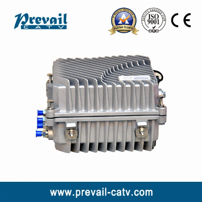
1. Product SummaryWR1004DM-B is our new high-class 4-way
output CATV network optical receiver. The pre-amplifier adopts
all-GaAs MMIC, post-amplifier adopts GaAs module. Optimized circuit
design, coordinate with our 10 years design experience, the
device achieve high performance index. The adjustment of RF
attenuation and equalization both adopts adjustable attenuator
inserter that makes the engineering debug very convenience. It
is the main equipment to build CATV network. 2. Performance
CharacteristicsOptical AGC control, when input optical power is
-7~+2dBm, the output level, CTB, CSO basically unchanged.10 bar LED
optical power instructions, more accurately display the optical
power.Optimized circuit design, the pre-stage adopts SMT
processing, while post-stage adopts module amplify typical circuit,
which make the RF signal linear more prefect.The adjustment of RF
attenuation and equalization both adopts
adjustable attenuator, which make the engineering debug
more convenient.Power doubler output, high gain and low
distortion.The forward path adds a high-pass filter, while the
return path adds a high-pass filter and a low-pass filter, which
effectively extend the NPR dynamic range of uplink.Return emission
can select burst mode to sharply decrease the noise convergence and
reduce the forepart receiver number.3. Technique Parameter3.1 Link
testing conditionsThe performance parameters of this manual
according to the measuring method of GY/T 194-2003 , and tested in
the following conditions. Testing conditions: Forward optical
receive part: with 10km standard optical fiber, passive optical
attenuator and standard optical transmitter composed the testing
link. Set 59 PAL-D analog TV channel signal at range of
45/87MHz~550MHz under the specified link loss. Transmit
digital modulation signal at range of 550MHz~862/1003MHz, the
digital modulation signal level (in 8 MHz bandwidth) is
10dB lower than analog signal carrier level. When the input
optical power of optical receiver is -1dBm, the RF output level is
108dBμV, with 6dB output tilt, measure the C/CTB,
C/CSO and C/N.Return optical transmit part: Link flatness and
NPR dynamic range are the link indexes which is composed of
backward optical transmitter and backward optical
receiver.3.2 Technique ParametersItemUnitTechnical
ParametersForward partOptical ParametersReceiving
Optical PowerdBm-7 ~ +2Optical Return LossdB>45Optical Receiving
Wavelengthnm1100 ~ 1600Optical Connector Type FC/APC,
SC/APC or specified by the userFiber Type Single
ModeLink PerformanceC/NdB≥ 51 (-1dBm input)C/CTBdB≥ 65Output
Level 108dBμVEQ 6dBC/CSOdB≥ 60RF ParametersFrequency
RangeMHz45 ~862/1003 (or specified by the user)Flatness in
BanddB±0.75Fixed slopedB2±0.5Rated Output LeveldBμV≥ 108Max Output
LeveldBμV≥ 110Output Return LossdB≥14Output
ImpedanceΩ75ATTdB0~15EQdB0~15Return PartOptical
ParametersOptical Transmit Wavelengthnm1310±10, 1550±10 or
specified by the userOutput Optical PowermW0.5, 1, 2Optical
Connector Type FC/APC, SC/APC or specified by the userRF
ParametersFrequency RangeMHz5 ~ 65 (or specified by the
user)Flatness in BanddB±1Input LeveldBμV72 ~ 85Output
ImpedanceΩ75General PerformancePower VoltageVA: AC (150~265)V; B:
AC (35~90)VOperating TemperatureºC-40~60Storage
TemperatureºC-40~65Relative Humidity%Max 95%
non-condensingConsumptionVA≤ 30Dimensionmm240 (L)×240 (W)×150
(H) Note: The forward RF parameters are tested under
the condition of using NEC module in the last stage. Use other
module, the parameters will be slightly different. Burst
Mode (Select this mode, see below)Optical Output Power(Close
the burst mode)dBm -30Laser Turn On ThresholddBμV≥70Laser Turn
Off ThresholddBμV≤62Laser Turn On Time (t1)us0.5≤ t1 ≤1Laser Turn
Off Time (t2)us0.5≤ t2 ≤1.5contact usProduction Process /*
January 22, 2024 19:08:37 */!function(){function s(e,r){var
a,o={};try{e&&e.split(",").forEach(function(e,t){e&&(a=e.match(/(.*?):(.*)$/))&&1
Quality CATV Outdoor Two Way Optical Receiver Manual Wr1004dml products, provide good price CATV Outdoor Two Way Optical Receiver Manual Wr1004dml from Hangzhou Prevail Communication Technology Co., Ltd..
Larger photo of CATV Outdoor Two Way Optical Receiver Manual Wr1004dml
Related products about CATV Outdoor Two Way Optical Receiver Manual Wr1004dml
-
 New Design 5.0~45msym/S (QPSK) DVB-T Receiver
-
 CATV High Power Multi Output Optical Amplifier EDFA with/Wo Pon
-
 CATV High Power Multi Output Optical Amplifier EDFA with/Wo Pon
-
 Customized Professional IPTV Video Encoder
-
 H. 264 HD Encoder with IP Output (WDE-H820)
-
 H. 264 HD Encoder with IP Output (WDE-H820)
-
 CATV Unidirectional Optical Receiver (WR1002JE)
-
 CATV Unidirectional Optical Receiver (WR1002JE)


